Tuesday 29 May 2012

Cooling system

Internal combustion engines have improved over the years but they are still about 30% efficient. The other 70%  is lost through heat, this heat is removed from the engine using the cooling system to prevent it from over heating and keeping it around 80 degrees Celsius The heat is removed by air flowing through the radiator. In the radiator/cooling system there is a mixture of water and antifreeze. The cooling systems job is not only to remove the heat from the engine but also to bring the engine to operating temperature as quickly as possible because the engine wears out more and creates more pollution when it is cold. The thermostat is used to bring the engine to operating temperature by blocking off the radiator and forcing the coolant to circulate around the block (where the heat is created). When the coolant reaches operating temperature the thermostat opens to allow the coolant to cool down through the radiator, then when it cools down the thermostat closes again. A fan is fitted to the engine or radiator to keep the air flowing through the radiator when the vehicle is stationery.

Experiment


Pressure testing


Pressure testing is used to check the cooling system for leaks by pressurizing the coolant with air. If there is a leak the pressure will go down over time (the gauge will go down)


Radiator

The radiator was visually checked for signs of corrosion or damage. The cap is also checked for damage and pressure tested.

Damaged radiator

Coolant testing (specific gravity)


The coolant is checked using a hydrometer. It indicates if there is enough antifreeze in the cooling system and what stat it is in.

Hoses


The hoses are visually checked for signs of wear like cracks

Thermostat


The thermostat is checked to see if it opens and closes at the right temperature by taking it out of the engine and placing it is a pot of water that is at the manufacturer's specified temperature.

Fan


The working condition of the fan is checked by bypassing the fan switch. If the fan does not go on there may be a fault with the relay, wires or the fan its self. The fan can be connected to power directly to see if it works. The switch can be checked by getting the engine up to operating temperature while the car is stationery.

Water pump and belts


The water pump is checked by removing its drive belts and turning it by hand, it should turn smoothly if it doesn't it will need to be replaced. The drive belts are checked for wear and that they are correctly adjusted.

Reflection


The cooling system is very important to ensure that the engine works correctly. If the engine over heats it could blow the head gasket or cause the engine to seize. If the thermostat stays closed the temperature will increases until the engine over heats as it does not allow the coolant to go to the radiator. If the thermostat stays open or opens at the wrong temperature it may result in the engine taking a long time to get to operating temperature or it may stay at a low temperature. If the fan does not work the car will over heat while stationery.

Monday 28 May 2012

Diesel ignition timing (mechanically controlled injection)

Diesel engines ignite the fuel using the heat created by high compression (does not have spark plugs). The timing of the engine is controlled by the fuel injected into the cylinders if the fuel is injected to early the timing will be premature and if it is too late the timing will be retarded both resulting in a lack of power.

Experiment 


We set the timing for a Mazda diesel engine. First we loosened the bolt, in the middle of the four high pressure lines that go to the injectors, on the diesel pump and put the DTI gauge in its place. Then we turned the crankshaft to 30 degrees before T.D.C and zeroed the Gauge. Then we turned the crankshaft to 2 degrees after T.D.C. We then loosened the diesel pump so that it was able to pivot, moved it so that the reading on the Gauge matched up with specifications and then tightened the diesel pump again. We removed the DTI gauge  and replaced the bolt.

Reflection


The diesel pump from the engine we worked on is very similar to the distributor on most petrol engines as far as timing goes. The method we used is called static timing (engine is stationery).

 DTI Gauge connected to the diesel pump
 Off car injector testing
 Off car glow plug testing
Testing the glow plug with a multimeter (ammeter) to see if it is drawing amps. This can be use to check if the glow plugs are working in the engine. If there is no current drawn it means that the glow plug is not working.

Thursday 24 May 2012

Oscilloscope

An oscilloscope is a device that displays voltage over a period of time. It displays the information on a graph with voltage on the Y axis and time on the X axis. In automotive the oscilloscope is used to measure sensors and actuator that have variable voltages that can not be seen with a multimeter like injectors, ignition pulses, MAP sensors, oxygen sensors etc. An oscilloscope can be used to diagnose engines and sensors to find faults or abnormal outputs.

Injectors

In an injector there are solenoid that is controlled by the ECU according to the engine's timing. When the solenoid receives power it opens up to allow the pressured fuel in the fuel rail to squirt into the cylinders. The  coil in the solinoid has resistance that according to ohm's law it means the volts should go down (as shown in the picture below) when the power is removed the voltage goes back up but it is noted that there is a voltage spike, a voltage spike occurs when a magnetic field collapses.

When the engine speed is increased the injectors stay open longer to run the engine richer.

Ignition

The ignition voltages are similar to that of the injectors


When the engine speed increases the number sparks also increase


Oxygen sensor

The oxygen sensor voltage oscillates up and down when the car is idling. When the engine speed is increased the voltage will oscillate slower.


Wednesday 23 May 2012

Vacuum testing

When the engine turns the movement of the pistons combined with the opening and closing of the valves work as a pump. It pumps air from the intake and pushes it out the exhaust. When the throttle is closed a vacuum or a low pressure area is created in the intake manifold because the engine pumps the air from the intake manifold and the throttle butterfly prevents air entering from the atmosphere. Vacuum can be defined as a area that has less pressure than its surrounding atmosphere.

Experiments


We connected the vacuum gauge to the intake manifold between the map sensor and the manifold. When the engine idled the vacuum was at 16in. Hg (inches of mercury). When the engine speed increased the vacuum went down to about 6 in. Hg. We then disconnected one spark plug wire (HT lead) and saw that the vacuum gauge had a small fluctuation. Then were removed one spark plug which made the gauge fluctuate a lot between 10 and 15 in.Hg.

Reflection


The vacuum gauge can be used to check that the intake manifold has the correct vacuum. It can also indicate if there are leaks in the manifold, if there is a cylinder that is misfiring or if there is a mechanical fault (air leak past the valves not sealing properly, damaged piston/rings. Can use a compression tester to find the fault) within one of the cylinders (removing one spark plug could simulate this). If the vacuum starts to get less after about 15 seconds there may be a obstruction in the exhaust.


Tuesday 22 May 2012

Fuel pressure

The fuel pump, pumps the fuel from the fuel tank through the filter to the fuel rail and then into the cylinders via the injectors. The pressure of the fuel is controlled by the fuel pressure regulator on the end of the fuel rail. The fuel pressure regulator works with vacuum from the engine. The faster the engine goes the less vacuum it creates in the manifold which means that the regulator would be closed more. When the regulator closes it creates a higher pressure in the fuel line (by restricting the flow or blocking off the fuel at the end of the fuel rail)  which forces more fuel through the injectors into the cylinder.

Experiment


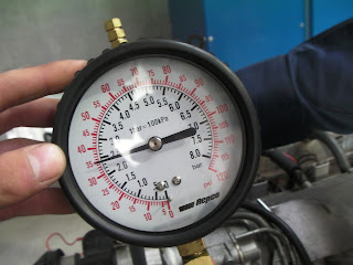
We connected a fuel pressure gauge to the fuel line after the filter. We started the engine and checked the gauge the reading was about 2.5 bar when we revved the engine the pressure increased to about 3 bar. To simulate the engine at full speed the vacuum hose can be disconnected from the fuel pressure regulator.

Reflection


The fuel pressure gauge can be used to see if the fuel pump is working and to check if the fuel pressure regulator is working properly. when the engine is idling and then the regulator vacuum hose is removed the pressure should increase in the fuel line. If it remains the same there may be a problem with the fuel pressure regulator. A flow test is done to see how much fuel is pumped out over a certain amount of time. The fuel supply pipe is disconnected and placed in a bottle or any other container then the time it takes to fill up is measured. The flow rate is equal to the amount (size of the container) divided by time (how long it takes to fill up the container)


Fuel pressure gauge

Gauge at idle speed

Wednesday 16 May 2012

Short Block


The short block is the main part of the engine (like a computer's mother board). Everything is connected to it. Engine blocks are made of cast iron or aluminium (in high performance engines). The cylinders and bearing saddles are machined with precision, to create the correct fit for the main bearings and the pistons, which increases the engines efficiency and it reduces wear. The block contains the crankshaft and pistons, in some cases it also contains the camshaft, lifters, valves and push rods depending on what type of engine it is. In the block the pistons' reciprocating motion is converted to rotational motion by the crankshaft. The block has channels and cavities like pipe lines to allow water to pass through to cool it down and for oil to be directed to engine parts that need lubrication.

Experiment


Block


I measured the cylinders in three places and then in another three places in another direction (at a right angle to the first three measurements) I did this to find out if the cylinders were worn, if they have taper or ovality. I then checked to see if the block's surface was warp by placing a straight edge on it at different places and measuring the gaps with a feeler gauge.

Pistons

I measured the piston diameters with a micrometer to check if they are worn. Then I removed the rings and cleaned the groves. When the "new" rings were fitted i checked the gap between the ring and the grove. Before I replaced the rings I check the ring end gaps by placing the ring in the cylinder and measuring the gap with a feeler gauge. If the gap is to small the rings could break when the engine heats up.

Crankshaft

 With the crankshaft out I measured the main bearing journals and the big end journals in two places and then again in two places at right angles to the first measurements. This it to check for taper or ovality. I then put the crankshaft back in its place and put one piston in. I placed a piece of plastic gauge on one of the main bearing journals and one on the big end journal and put the caps on and torqued them to the manufacturer specifications. Then took them off again and measure the plastic gauge. This was to check the gap between the journals and the bearing shells where the oil moves through. To measure the crankshaft end play I placed the DTI gauge on front of the block with the gauge on the crankshaft and move the crankshaft back and forth with a screwdriver. I then measured the big end play with a feeler gauge.


Reflection


The measurements that I did was to check the clearances and gaps in the engine. It will indicate weather or not the the parts are worn. If the parts are worn it means they need to be repaired or replaced. The clearances are also to compensate for the metal expanding when the engine heats up.


Monday 7 May 2012

Oil Pump

The oil pump, pumps the oil to all the parts of the engine that need lubrication. eg bearings, cylinder head, cylinder/pistons. The oil pump consists of two gears that create a suction as they turn that sucks up the oil in the sump through the pick up then they push the oil through the filter and oil gallery that supplies all the moving parts that need oil. The oil pump is a vital component in the engine, if the engine has no oil it will seize. The oil in a engine also works as a coolant.

Experiment

To check the oil pump I first did a visual inspection of it to check that everything looks like it is in good working order. Then I measured the gap between the straight edge and the gears I then checked it with the specifications for the engine. Did the same with the gap between the two rotors and the gap between the outside rotor and the casing of the oil pump.


Reflection

The gaps measurements were within the specifications which meant that the oil pump does not need to be replaced or repaired. The gaps in the oil pump shows how important oil and oil filter replacements are. If foreign materials like sand or dust get into the oil it could wear down the mechanical moving parts like the oil pump reducing their effectiveness.